Chapter 8 Arduino Interfacing
Arduino is a tool for interacting with the physical world through sensors. It’s an open-source physical computing platform based on a simple and inexpensive micro-controller board, and a development environment for writing software for the board. It is an open-source electronics prototyping platform.
can be used to develop interactive objects, taking inputs from a variety of switches or sensors, and controlling outputs, such as LED lights, motors, and other physical outputs. Arduino projects can be stand-alone, or they can be communicate with software running on your computer.
The Arduino micro-controller is powered through the USB cord or with batteries.
8.1 Microcrontroller
The Arduino is a microcontroller with 6 analog in ports, and 13 digital ports. The digital ports can be either inputs or outputs. The microcontroller contains a microprocessor, memory or RAM, some flash memory, a clock (oscillator), and an A/D (analog to digital) converter. All of these components are integrated into a small chip, which is at the heart of the Arduino board. The common ATmega328 chip, for example, has 2 kB of RAM, 32 kB of Flash memory that can be programmed, 20 MHz oscillator clock, and 32 pins. This microcontroller costs less than USD 1.50, if purchased in high volume.
There are many Arduino boards with different configurations. These boards pack USB connectivity, built-in LEDs, power jack connection, and separate pins for inputs and outputs. Additionally, shields are available to expand the functionality for wifi, GPS, stepper motor control, and other features.
The Arduino is used for proto-typing and at the core of many Kickstarter projects. Recently, it has also been used in educational and teaching projects (Esposito et al. 2015).
8.2 First Arduino Program
The Arduino software is downloaded and installed from www.arduino.cc. It comes with several sample programs that will be useful templates for further programming.
The first program that you generally run is the "Blink" program that will make an LED blink at the desired rate. The easiest program will in fact use one of the LEDs that is directly built into the Arduino UNO board. It is controlled via pin 13. The tutorial is available online at https://www.arduino.cc/en/Tutorial/Blink.
First, connect the Arduino board via the USB cable to the computer. Then run the Arduino software and compile the "Blink" program. It is important to select the proper "Serial Port". From the menu, choose "Tools", then "Serial Port", then select the "USB" port, see Fig.@ You may also have to set the Board type, again in the "Tools" menu. Once setup, you can then transfer the program to the Arduino board, by choosing the "right arrow" button on the top left of the program, see Fig.@.
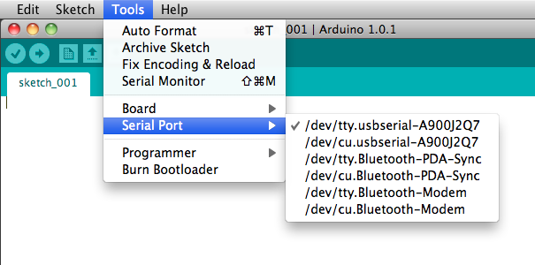
Select the USB port from the Serial Ports, so that the Arduino program knows where to send the compiled program.
8.3 Serial Communication
There is a built-in library that supports serial communication with a computer. The Arduino board sends messages back to the computer. It is initialized with the command Serial.begin(9600); in the setup(). A number or text can be output with the command Serial.println(voltage);, where voltage is the measured voltage, for example. Make sure to use the proper quotation sign, if you are sending text as the compiler is very specific. Each line must be terminated with a semicolon in the Arduino C script.
8.4 Sensors and Physics
There are two aspects to Arduino projects. The first one, we will want to integrate sensors, such as the temperature sensor and convert the electrical signal based on the specifications given by the manufacturer; this is the engineering part of the problem. In the second part, the physics portion, we want to test the limits and ask questions such as, what is the resolution of this sensor, what is the response time, specific heat? How can the sensor be calibrated and tested for accuracy? For each question, we would build a hypothesis and a strategy plan for testing. We would then be able to quantitatively determine some of this properties, compare them with specifications that are published and add our own results.
8.5 Bot
A bot, such as SparkFun’s RedBot, is a robotic platform that uses sensors to move the vehicle. The Arduino micro controller contains the code to analyze the sensor inputs and provide the commands to the motor. Two gear motors control the motion of the 3-wheel bot. The motors each provide a torque of about 0.078Nm. By controlling the speed of each motor, the bot can be steered. In order to avoid obstacles and follow a path, sensors are used. The line follower sensor measures the amount of reflected infrared light and can detect changes from dark to light on the surface. It should be mounted about 3mm away from the surface. It has 3 connecting wires, GND, VCC, and OUT. The GND and VCC are connected to the 5V potential difference from the Arduino. The Accelerometer detects hitting another object or sudden vibrations.
The RedBot can be programmed more easily with the available RedBot library, which also includes documentation. It includes three classes of objects:
- RedBotAccel
- RedBotMotor
- RedBotSensor
Once, you include the library, you can import its function with: #include <RedBot.h>, and use its functions, such as drive(int speed), stop(), brake(), leftDrive(int speed), and rightDrive(int speed), where speed is an integer from -255 to 255. A negative number would make the motor go backwards.
#include <RedBot.h>  // This line "includes" the RedBot library into your sketch.
// Provides special objects, methods, and functions for the RedBot.

RedBotMotors motors; // Instantiate the motor control object. This only needs
// to be done once.

void setup()
{
  motors.drive(255);   // Turn on Left and right motors at full speed forward.
  delay(2000);         // Waits for 2 seconds
  motors.stop();       // Stops both motors

  delay(5000);
  // pivot -- spinning both motors CCW causes the RedBot to turn to the right
  motors.rightMotor(-100); // Turn CCW at motorPower of 100
  motors.leftMotor(-100);  // Turn CCW at motorPower of 100
  delay(500);        // for 500 ms.
  motors.brake();    // brake() motors
  delay(500);        // for 500 ms.
}

void loop()
{

}
The library also includes several examples, such as BasicTest, DriveForward, and LineFollowing_IRSensors. Here is a snippet of the LineFollowing Sensors:
#include <RedBot.h>
RedBotSensor IRSensor1 = RedBotSensor(A3); // initialize a sensor object on A3
RedBotSensor IRSensor2 = RedBotSensor(A6); // initialize a sensor object on A6
RedBotSensor IRSensor3 = RedBotSensor(A7); // initialize a sensor object on A7

void setup()
{
  Serial.begin(9600);
  Serial.println("Welcome to experiment 6!");
  Serial.println("------------------------");
}

void loop()
{
  Serial.print("IR Sensor Readings: ");
  Serial.print(IRSensor1.read());
  Serial.print("\t");  // tab character
  Serial.print(IRSensor2.read());
  Serial.print("\t");  // tab character
  Serial.print(IRSensor3.read());
  Serial.println();
  delay(100);
}
8.6 Light Emitting Diodes
Light emitting diodes or LEDs are generally based on two semiconductors with different properties. One semiconductor is a p-type, while the other is an n-type. The charge carriers in the p-type material are holes, and the carriers in the n-type material are electrons. Each semiconductor has a characteristic band gap (forbidden energy region for electrons). By creating a p-n junction, current is easily conducted in one direction, but not the other. At the junction, electrons and holes tend to recombine and thereby emit light.
Due to the asymmetry of the junction, the LED has a cathode and anode, or a positive and negative leg. Therefore, it matters how the LED is connected. One leg is longer (anode) and denotes the positive end.
Depending on the wavelength of emitted light, the applied voltage for emittance changes. Typical values range from about 1.8V for red light to about 3.3V for blue light. Applying a voltage that is too low, will not be sufficient for recombination to occur and so no light is emitted. A voltage that is too large will fry the LED. Unlike ohmic resistors, where the current increases linearly with the increased voltage, the current in a semiconductor increases exponentially with the voltage. Therefore, applying a slightly higher voltage leads to a very large current that will become quickly destructive to the narrow gap in the LED.
Typically, for a diode, include an LED, the current - voltage behavior can be modeled with the following equation:
\[\begin{equation} I(V) = I_0 \left( \exp{\left[ \frac{q V}{k_B T} \right]} - 1 \right) \end{equation}\]
with \(k_B\) as the Boltzmann constant, \(T\) as the temperature, and \(q\) the charge of the carrier.
The Arduino board generally provides 5 V, therefore the red LED cannot be directly connected. The voltage must be reduced first. This can be done by inserting a resistor into the circuit. Part of the voltage drop will be across the resistor. For example, we would like to connect a red LED, such that the resistor will have a voltage drop of 3.2 V, such that the remaining voltage drop of 1.8 V is across the