Lab 10 RC Circuits
An RC circuit has a battery connected to a resistor R and capacitor C in series. The maximum charge that can be stored on a capacitor is \(Q = C \cdot \Delta V\), where C is the capacitance measured in units for Farad (F), and \(\Delta V\) is the electric potential across the capacitor. In particular, if the capacitor is “empty” or uncharged, then Q = 0, since \(\Delta V\) = 0. At that moment, the full potential from the battery is across the resistor and a current \(I = emf/R\) is running. This current starts to charge the capacitor. The time to charge the capacitor to 63% takes (tau) \(\tau = RC\) time. Indeed, if you multiply Ohm with Farad you get seconds. This is the time constant of an RC circuit. The resistor limits the speed of charging and discharging. For the charging process, the voltage across the capacitor as a function of time t is \(\Delta V(t) = emf [1 - \exp(-t/RC)]\), where emf is the voltage of the battery. You can show \([1 – \exp(-1)] = 0.63\); so waiting for 3 time constants will charge the capacitor to \([1 – \exp(-3)] = 0.95\), or 95%. Most physicists (and economists) will know those numbers by heart. If the battery is disconnected, the capacitor will discharge according to \(\Delta V(t) = emf [exp(-t/RC)]\).
10.1 Goals
- Build an RC circuit and determine the time constant by measuring the resistance and capacitance.
- Measure the time constant first with a DMM
- Change the resistance and re-measure the time constant.
10.2 Prediction
- Draw a circuit with a battery, resistor, and capacitor in series. Add a voltmeter that will measure the voltage across the capacitor.
- Make four graphs: two graphs of the voltage versus time for charging and discharging; secondly two more graphs with teh current versus time for charging and discharging.
10.3 Equipment
- DMM
- Capacitance meter ELIKE DT6083
- 10 V power supply (as battery)
- resistors and capacitors
- Breadboard and wires
10.4 Procedure
- Take a resistor and determine the resistance using the DMM.
- Build a resistor-capacitor-battery circuit with all elements in series.
- Measure the electric potential (voltage) across the capacitor.
- Use a stop watch and record voltage vs. time after you disconnect from the battery and create a resistor-capacitor circuit. Record voltage versus time for charging and discharging.
- Repeat the measurement and this time record the current versus time.
- Determine the time constant from the graph and compute the capacitance.
- Repeat the measurement and observe charging of the capacitor as well as discharging. Ascertain that the capacitor is fully charged before starting the measurements.
- Determine the uncertainty of the capacitance.
- Change the resistance and remeasure the voltage versus time for charging and discharging. Compare with your predictions.
- Use different methods to determine the best values for time constant \(\tau\).
10.5 Measurements
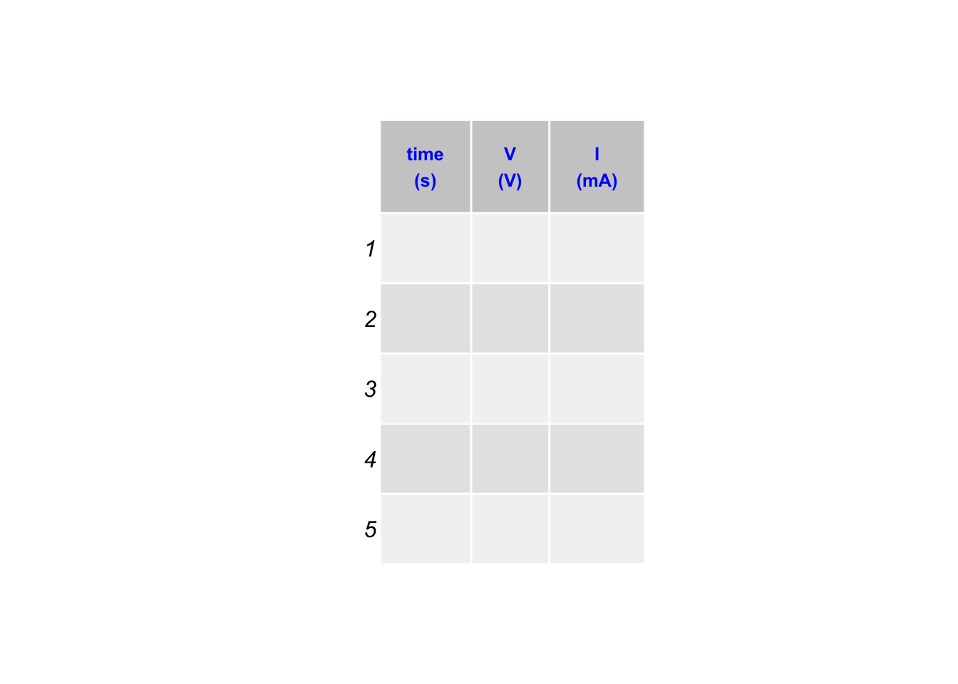
Create the following tables with periodic measurements:

10.6 Graph
Make 4 graphs for voltage and current versus time for charging and discharging. Compare the graphs with the predictions.
10.7 Summary
Summarize your results with regards to the goals. Discuss the four graphs for voltage and current versus time for charging and discharging. Describe the most accurate to obtain the time constant for an RC circuit.