Lab 11 Black Box - Part 1
In this lab, you will apply your skills of electric circuits. Inside a black box, there is a circuit hidden, and it is your challenge to find out what the circuit is. The correct analysis of accurately measured data yields a unique circuit. The boxes contain the following elements: ohmic resistors, diodes, and light bulbs.
11.1 Diode
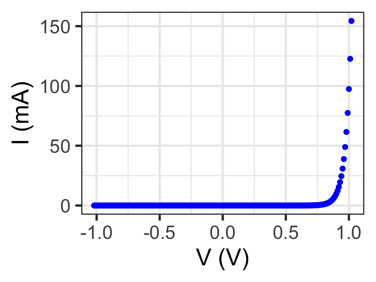
Unlike a resistor a diode is a non-ohmic device. While resistors are made from metals, a diode is made from two semiconducting layers, one layer is hole-doped and the other layer is electron-doped. When placed in series, the two semiconductors create a pn-junction (same as a solar cell). The common diode used in the lab has the following current behavior,
\(I = \alpha \left[ \exp(\beta V) -1 \right]\)
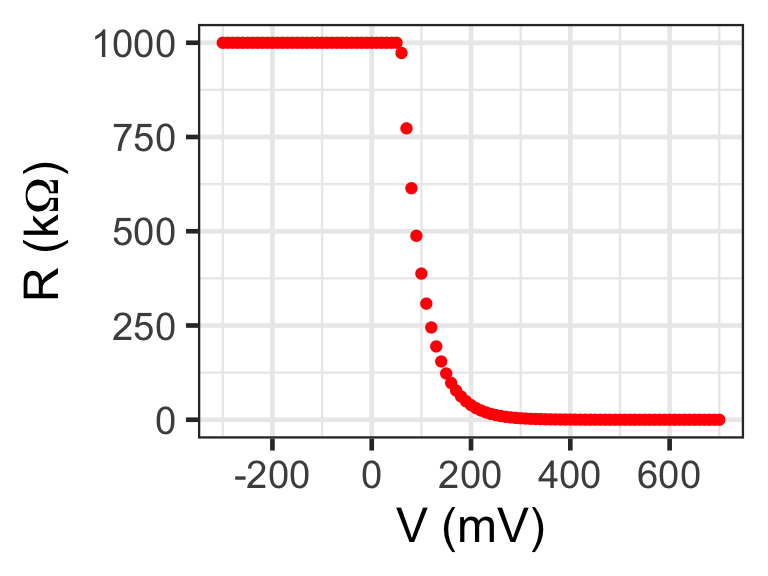
with \(\alpha\) = 10\(^{-8}\) mA, and \(\beta\) = 23 V\(^{-1}\). The exponential form is of the current is shown below. Qualitatively, you can say that current flows only in one direction, but in the reverse direction, there is no current. The effective resistance of the diode depends on the electric potential across it. In reverse \(\Delta I = I_f - I_i\) is very small, as the curve is almost flat, so \(R = \Delta V / \Delta I\) becomes extremely large, which means that there is no current flowing. However, in the forward direction, \(\Delta I = I_f - I_i\) is small first and becomes larger, so for small voltages \(R = \Delta V / \Delta I\) is large but becomes smaller for high applied electric potentials. In other words, if you were to put this diode in series with a resistor, then for low applied voltages the diode dominates, but for high applied voltages, the net resistance would be almost equal to the resistor. On the other hand, if a diode is in parallel with a resistor, then for low applied voltages and negative voltages, the current would run through the resistor, but as the voltage becomes large enough, the resistance of the diode drops and almost no current would flow through the resistor any longer. What does “large enough” mean? This depends on the diode, so let us plot the “effective” resistance for the diode equation above. The following graph shows how the resistance decreases with increasing applied voltage. The resistance is capped at 1 M\(\Omega\).
11.2 Goals:
- Learn about diodes, which have a directionality.
- Hone your skills to measure current and electric potential
- Measure the I-V curve of complex circuits with both resistors and diodes.
11.3 Prediction:
In addition to the circuit diagram, draw 2 topologically different circuits that have exactly two resistors and 1 diode (indicate the direction of the diode, too).
Draw the I-V curve for the drawn circuit with 2 resistors and one diode. The values are \(R_1\) = 90\(\Omega\) and \(R_2\) = 30\(\Omega\). Assume that A is connected to ground, and B is applied 2 V.
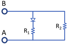
Circuit with 1 diode and 2 resistors, connect A to low-potential.
11.3.1 Caution
- You should not apply currents larger than 0.2 A. The power supply may have a limiter built in.
11.4 Equipment
- Breadboard with resistors and diodes
- Variable voltage source (0.1 V – 3.0 V)
- 2x DMM and wires
11.5 Procedure
- Use a breadboard to add one diode and 2 resistors. Create the circuit shown in the Figure.
- Measure the I-V curve. Measure both negative and positive potentials, by reversing the leads on the power supply.
- Note: Make sure to measure a sufficient number of data points. Remember that the exact voltage - i.e. 2.00V - is not important, rather record voltages accurately - i.e. 1.97V. Record many data points to quickly obtain the right shape of the curve, take more data points in voltage sections, which are not linear.
- Compare the results with your predictions.
- Explore what happens if you reverse the diode.
11.6 Graph
Draw an I-V curve of the circuit. Show how you can analyze the slopes to find the resistor values and the diode direction.
11.7 Summary
Address the goals set forth and report on the slopes that you measured on the I-V curve at high electric potentials either negative or positive. Discuss their interpretation. Include uncertainties of the resistance values that you measured.