Lab 9 Electric Circuit with Light Bulb
We explore currents in a basic electric circuit by measuring the current versus voltage curves of conductors at different temperatures. Use the digital multimeters (DMM) INSTEK 8245 and BK 2703B/C to record the electric potential difference \(\Delta V\) and the current I. The device manuals are posted on Beachboard. Use a small power supply to change the electric potential (“voltage”) across a resistor and a light bulb. In each case, measure more than 15 data points to compute the resistance. Georg Ohm (the “Ge” is pronounced as in “guest”) found that in conductors, the resistance \(R = \Delta V / \; I\) is independent of the applied voltage, these materials are called “ohmic”. Hence, the resistance R in conductors only depends on the material and geometry, but not on the applied voltage, or the current.
In metals, the resistance increases with temperature approximately linearly.
In the Edison light bulb, the filament is made of tungsten. It is very thin, so it has a high resistance compared to the wire that delivers the electric potential to the bulb. The filament has a large electric field, which accelerates the electrons much more and creates more frequent collisions, which are the reason for heating. At temperatures above 2000 K, the hot filament starts to glow in the visible spectrum due to black-body radiation. At low voltages, the filament is at room temperature, but if 0.8 V or more is applied it starts to get very hot and the resistance increases with the higher temperature. Therefore, in a light bulb the resistance is either low (cold) or high (hot).
9.1 Goals
- Measure the I-V curve of (1) a resistor and (2) a light bulb
- Learn to make current and voltage measurements.
- Determine the resistance of the common metal resistor and the tungsten filament in the light bulb.
9.2 Prediction
- Draw an I-V curve (current vs. voltage) for a metallic resistor.
- Add an I-V curve with a different color for a resistor with higher resistance than the previous one.
- Draw an I-V curve for a light bulb. (Note that the filament in the light bulb is tungsten, a metal with a high melting point, gets hotter with more applied voltage. For metals, the resistance increases with temperature.)
9.3 Equipment
- 2 multimeters, one to measure current I and one to measure electric potential \(\Delta V\)
- several wires
- resistor and light bulb
9.3.1 Caution
- Make sure to turn off the Multimeter when not in use.
- Make sure that you understand the different configurations for either measuring current or electric potential. Read the manuals for the digital multimeters.
9.4 Procedure
- Build a circuit with the resistor and the power supply. Use a black cable for ground (-) and red cable for positive potential (+).
- Use one DMM and connect the wires to measure the electric potential \(\Delta V\) across the resistor. Make sure that you can vary the electric potential by using the power supply.
- “Break the wire” at one point and use the second DMM to measure current I. Make sure to correctly connect the wire to the DMM inputs.
- Record electric potential and current I; then use the knob on the power supply to change the electric potential. Ensure that you have at least 15 data points over a good voltage range from 0 to 3 V.
- Repeat for the light bulb. Note your observations, such as the voltage at which the light turns on.
- Compute the resistance and the standard deviation. If the standard deviation is large, repeat the measurement.
For the light bulb, you should measure the cold and hot resistance values separately. Be careful, that you use small voltage differences to compute the resistance, since it may not be linear for large voltage differences; i.e. measure the currents \(I_1\) and \(I_2\) at 2.0 V and 2.1 V, so \(\delta V = 0.1V\), and then compute the resistance \(R = (\delta V)/(I_2 - I_1)\).
9.5 Measurement
- Record the I-V curves for both the resistor and the light bulb

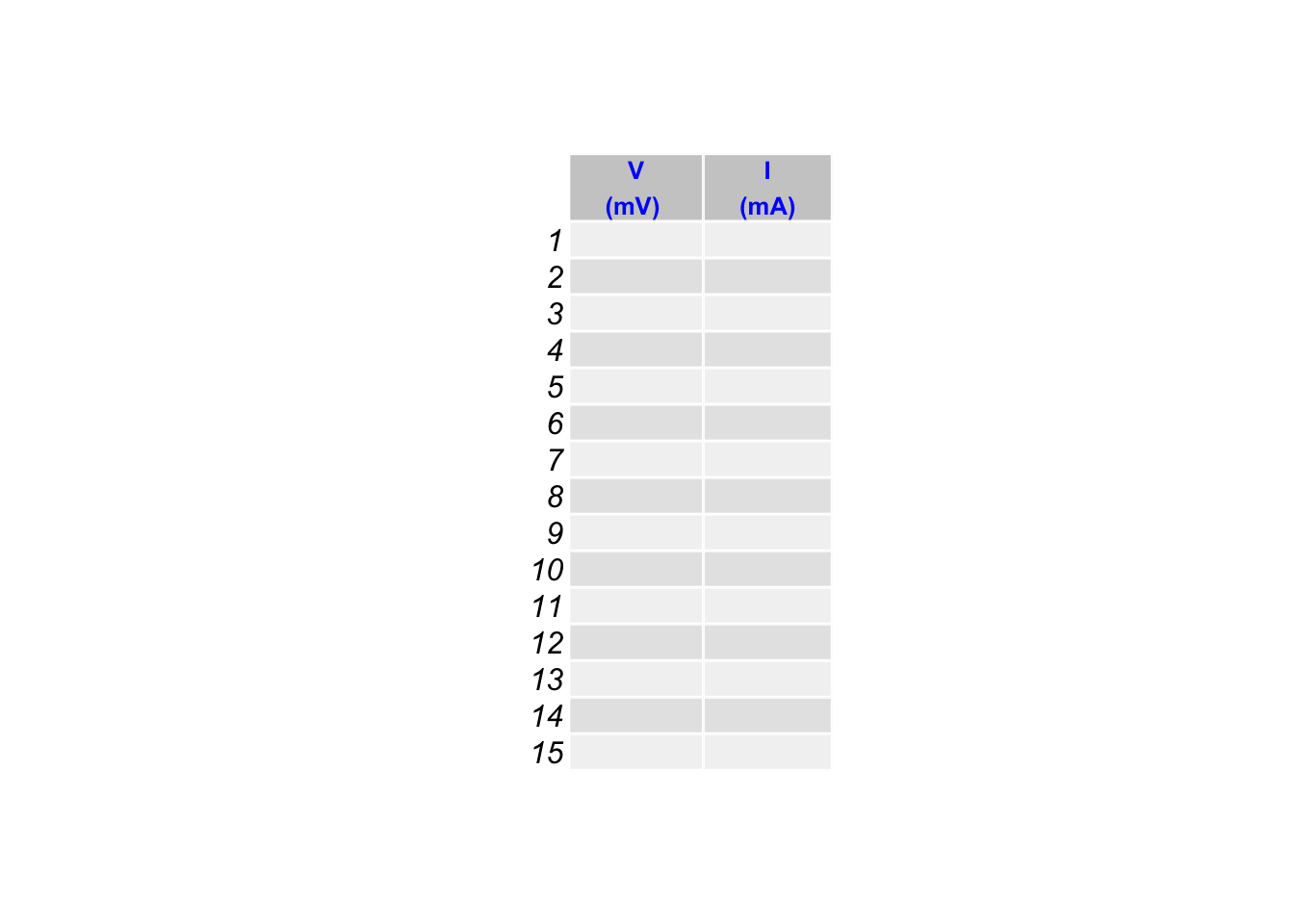
Compute the resistance \(R\) for different measurements. Note that for your resistance measurement, you can only chose points which are close together in voltage, so \(\Delta V = V_2 - V_1 <\) 0.1 V. Therefore, \(R\) is determined by taking two close data points from the above table, and computing the difference in electric potential and the difference in current. The slope is then the local resistance \(R\) at the midpoint of \(V = \frac{V_2 + V_1}{2}\).
Make a table with the results, include the propagated uncertainty:

- Repeat for the light bulb.
9.6 Graph
Make one graph with the I-V curve for the resistor and the light bulb. Find the most extreme points first and then determine the scales for graphing. Label each of the data sets clearly, or use different colors.
9.7 Summary
Discuss the I-V curve of the resistor. Explain the behavior of the light bulb using the argument of temperature and determine the voltage at which it turns on. List the average value for the resistor and include the uncertainty. Pay attention to the right number of significant digits. Discuss the results from the light bulb separately. In the reflection, discuss how you could use such a resistor as a temperature sensor.
9.8 Additional Reading
Breadboard: https://learn.sparkfun.com/tutorials/how-to-use-a-breadboard/all
2703C DMM User Manual: https://bkpmedia.s3.amazonaws.com/downloads/manuals/en-us/2703C_manual.pdf