Lab 8 DC Circuits with Connections in Series and Parallel
We explore currents and electric potential in more circuits with multiple resistor elements. The resistors can be arranged either in parallel or in series or a combination thereof. Here, electronic circuits are first designed on a “breadboard”. The breadboard connects wires without the need for soldering. Explore how the breadboard works using the provided wires and a DMM set to measure resistance. Points with almost no resistance are connected on the back side of the breadboard. If the resistance is large (“circuit is open”), then they are not connected. Once, you understand the breadboard, you can arrange two resistors in parallel or in series. The power dissipated in each element is the product of current running through the element and the voltage across it. In particular, the power consumpotion of the entire circuit is equal to \(P = I \Delta V\), where I is the current flowing out of the battery and \(\Delta V\) is the electric potential across the battery.
It will be helpful to remember that the node rule is charge conservation (\(I_{in} = I_{out}\)), and the loop rule is energy conservation (\(\sum \Delta V_i = 0\) V).
8.1 Goals
- Understand the connections of a breadboard and determine the resistance of resistors using a digital multimeter (DMM).
- Measure the electric potential for two resistors in series and in parallel; compare your results with the computed values.
- Using the provided resistors, create an effective circuit with 6666 \(\Omega\) (or as close as possible). Use less than 10 resistors in total.
8.2 Prediction
- Draw a circuit with two resistors in series and a second circuit with two resistors in parallel. Label the resistors \(R_1\) and \(R_2\).
- Calculate the current and electric potential across each resistor either in series or in parallel given a power supply with an electric potential \(\Delta V\) = 3.0 V. Apply the loop rule and the node rule to solve the problem.
- Which circuit configutation (series or parallel) uses more energy? Why?
- Given up to 10 resistors with 2000\(\Omega\) each and up to 10 resistors with 10\(k\Omega\) each, propose building an effective resistor that is close to 4770\(\Omega\) as possible and has the fewest possible number of resistors.
8.3 Equipment
- 2 DMMs to measure electric potential and current
- Box with different resistors
- Breadboard and wires
- 3.0 V or 1.5 V power supply
8.3.1 Caution:
- Make sure to turn off the DMM after use and when not in use.
- Avoid “shortening” the power supply; always have at least one resistor in the circuit!
- You should not apply currents larger than 0.2 A.
8.4 Procedure
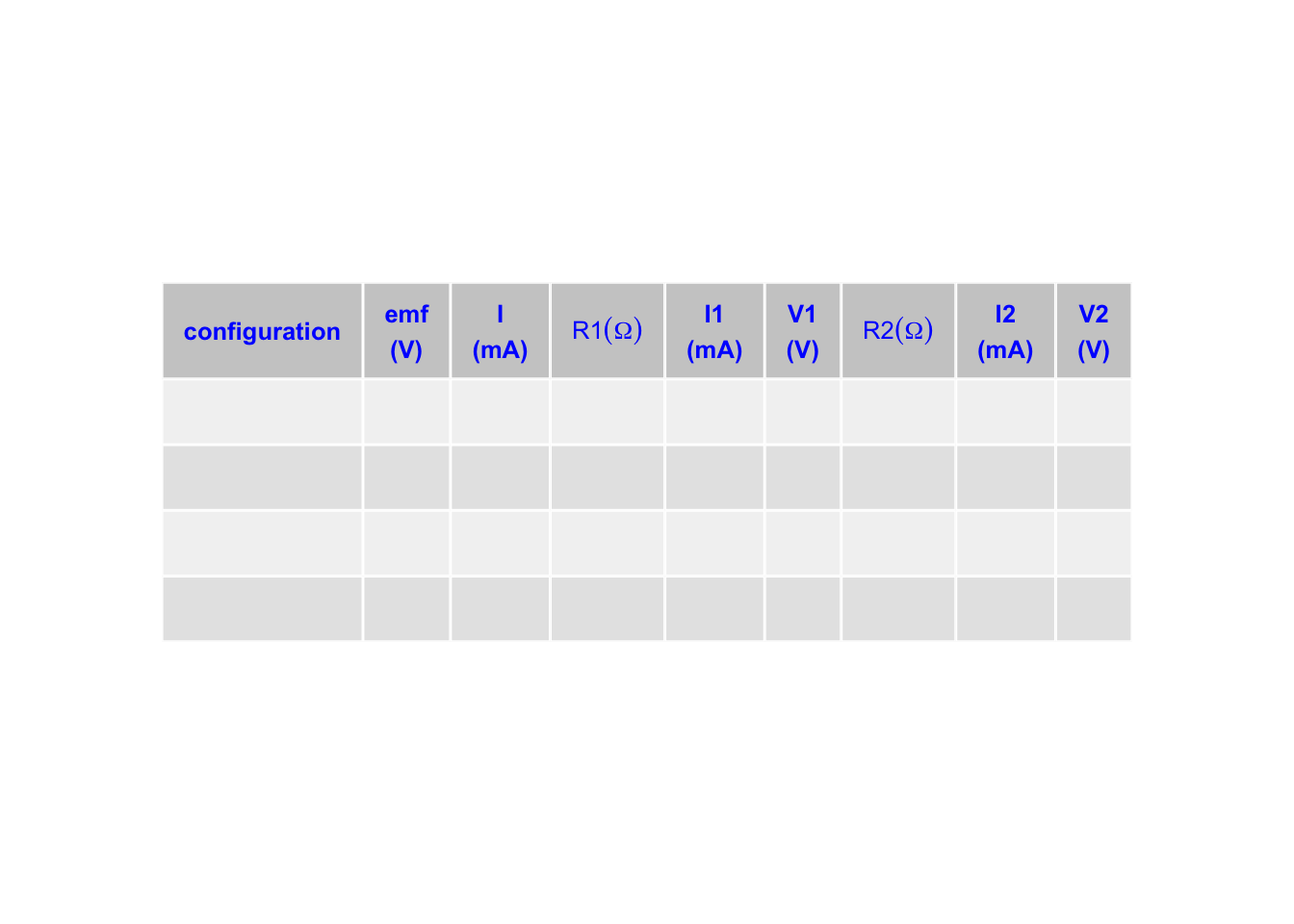
- Build a circuit with two resistors in series connected to the power supply. Measure the electric potential across each individual resistor and measure the current going through each resistor.
- Repeat measurement with both resistors in parallel.
- Use a table similar to this one:
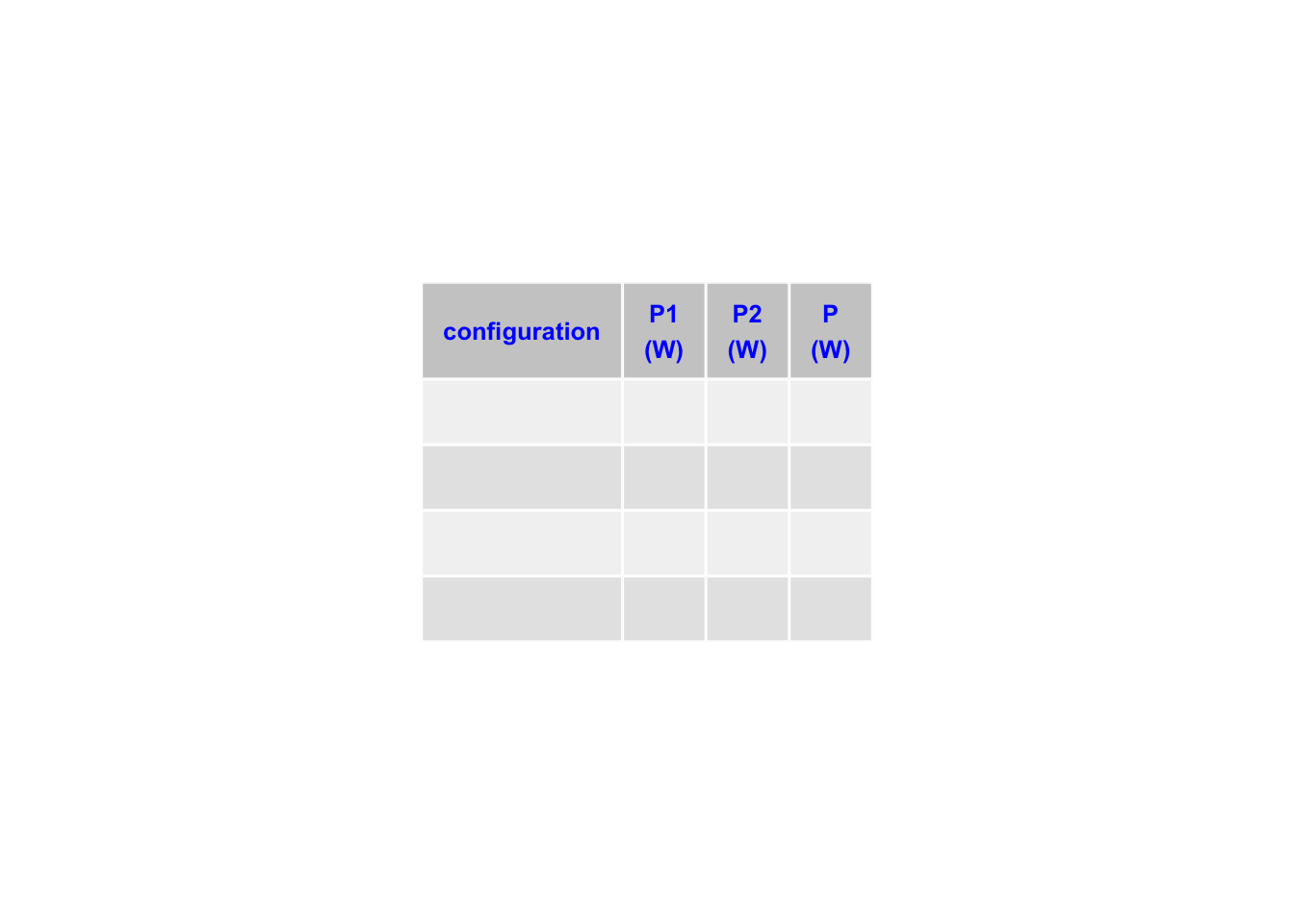
- Compute the power used in each resistor. The power dissipated by the resistor is \(P_i=\Delta V_i \cdot I_i\), where \(I_i\) is the current flowing through that resistor and \(\Delta V_i\) the electric potential across it. Make a table as follows, where \(P_1\) is the power dissipated by resistor \(R_1\), \(P_2\) by resistors \(R_2\), and \(P\) is the total power disspated in the circuit, where \(P = emf \cdot I\)
Which circuit uses the most power? Compare with your predictions. How is the total power \(P\) related to the power used by each element?
Create an effective resistor that has a value as close to the goal value as possible. Calculate the effective resistance of your design. Have the resistor checked by the instructor, who has a DMM with 4-digit precision.
If time permits, create a mixed circuit with 3 resistors that has resistors both in parallel and series. Determine the currrents, electric potentials, and power consumed by each element and compare with the total power consumption. Also explore building a voltage divider.
8.5 Graph
Create bar plots that show the power consumed in the entire circuit and each resistor for both configurations. Create a separate bar plot with the currents through each of the resistors (\(R_1\) and \(R_2\)) and through the battery for both configurations.
Include a schematic diagram of the effective custom resistor that you built and report both the predicted resistance and mesaured values.
8.6 Discussion
Which circuit uses more power, the series or parallel circuit? What did you learn about the current flowing through each resistor? How is current measured differently from electric potential?
8.7 Summary
Discuss circuits in series and parallel. Discuss current, electric potential, and power in all circuits. Desribe your process of building a custom effective resistor and discuss your result in the context of the class context.
8.8 Additional Reading
Breadboard: https://learn.sparkfun.com/tutorials/how-to-use-a-breadboard/all
2703C DMM User Manual: https://bkpmedia.s3.amazonaws.com/downloads/manuals/en-us/2703C_manual.pdf