
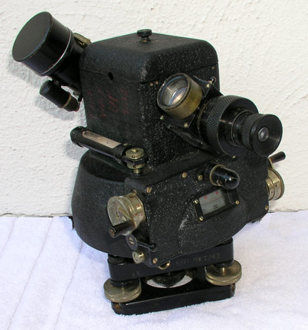
E. R. Watts & Son. Ltd., London MK I Balloon Theodolite.
This is the 1st version of an instrument in a series of theodolites that was the
standard in the meteorological services of the British Commonwealth. They
were designed at the Meteorological Office in collaboration with E. R. Watts
& Son LTD circa 1936. 5 different models were produced Mk I through MK V.
The models were produced as successive improvements over earlier models. This
example was produced in 1937 and refurbished by Watts in 1943 it is number 9 -
possibly the ninth Met Office Pattern theodolite produced.
In the Mark I instrument the micrometer tangent screw drives the elevation circle and circle is connected to the telescope through a bevel gear. This instrument had color filters that fit over the objective rather than later models where the filters fit over the eyepiece. This instrument has a variable focus objective and the eyepiece focus lacks markings that would have facilitated diopter referenced adjustment. Its battery box is built into the instrument. The instrument is smaller and lighter than succeeding instruments and it has a larger finder objective.
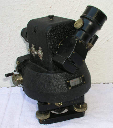
The second image shows the rear readouts of the circles. The micrometer drums can also be read from the rear of the instrument allowing a second observer to log the instruments position while the primary observer can keep the theodolite trained on the balloon. The mark 1 does not have a magnifying glass for reading the circles like later models and the circles are black and red on a silver background rather than white and red on a black background. Note the presence of the gun site on the main telescope it is mounted on the finder scope on later models.
In common with other land based balloon theodolites it has a telescope with a bent optical axis. A secondary wide-angle telescope using the same eyepiece selectable with a mirror. Follow this link for a more detailed description and Cutaway Illustration of the Watts MK I Balloon Theodolite.
Like the vast majority of balloon theodolites, the image in inverted when viewed in a Watts theodolite. All Watts Balloon theodolites feature micrometer drums that drive the circles with tangent screws. The tangent screws and micrometers can be disengaged for rapid motion and positively reengaged for accurate tracking.
These theodolites incorporate a lined gradicule to support the tail method of altitude determination. The spacing of the gradicule lines was changed during the evolution of the theodolite series. Slide rules manufactured as early as 1941 (and possibly much sooner) have notes explaining two procedures for calculations based on two gradicule line spacings. A Met. Office Instruction sheet dating May 1927 contains instructions for changing the length of the tail to match the line spacing of the gradicule, but I believe that this is to allow for small variations in the gradicule not, a change in manufacturing.
| Drive Type | Positively Engaging Tangent Screw | Compass | No |
| Display Type | Micrometer .1 degree | Levels | 1 tribrach base plate, 1 Inst, body bubble tube |
| Main Telescope | 35 mm 16x 2deg. | Mounting | Tribrach |
| Finder Telescope | 20mm
4.5x ?deg. single eyepiece |
Illumination | 2, 3
Volt lamps, scales reticule |
| Gun Site | Yes 1, on main telescope | Weight (theodolite only) | ? kg (Lighter than the MK II) |