


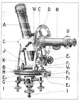
Prior to the Introduction of the Met. Office Pattern Theodolite in 1937, two models were in common use, the Cary Porter Model D, and the Watts Mark B theodolite. These are shown below. The Cary Porter theodolite was of the open frame type with verniers, and the Watts featured Micrometer Drums and a closed frame design - features which were retained in the Met. Office Pattern Theodolites that followed.
| Cary Porter Mark D | Watts Mark B |
 |
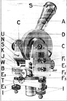 |
| A:
Right Angled Telescope B: Plate C: Bearings for Telescope D: Vertical circle E1,2: Tangent Screws F1,2: Tangent Screw Levers E3,F3: Clamp Adjusting Screw and Clamp G: Capstan Head Screw H: Horizontal Circle I: Leveling Feet J,K : Bubble Level and adjustment screw N: Telescope Focus Knob and eye-piece tube (Watts is fixed focus) S: Open sight (Watts only) V: Verniers (tenths of a degree, Micrometers used on the Watts) W: Window for Reading the Horizontal Circle (Watts only) U: Cover for gradicule adjustment screws |
|
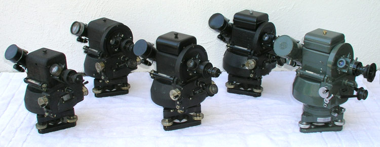
The Watts Meteorological Office pattern theodolite series includes 5 theodolite models. The series was in production from 1937 through the present. The company has existed in three forms during these years. E. R. Watts & Son, Hilger and Watts and currently Hall and Watts Defense Optics. These models were produced sequentially and represent refinements of previous models in the series. Watts theodolites are still in use in the United Kingdom and countries who were closely allied with the United Kingdom such as Australia and Canada.
The circles and the corresponding telescope movements, are operated by hand cranked 10 part micrometer drums attached to tangent screws. The azimuth and elevation are read from two circles arranged horizontally such that they can be viewed one directly above the other through a window with an engraved reference line. The window and micrometers are on the same side of the instrument as the eyepiece. The drum for the azimuth movement is on the observer's right. The drum for the elevation movement is on the observer's left. Each drum has a lever directly below that allows the operator to disengage the tangent screw for rapid movement Illumination is provided for the circles and the gradicule. The batteries are housed in the upper part of the body of the instrument. For the circles a small electric bulb is carried in a screened holder just above the front scale window. To illuminate the graticule a bulb is so arranged so that the beam of light is thrown on to a small mirror in the center of the telescope tube, whence it is reflected on to the prism and so in to the gradicule which appears dark against an illuminated field. The degree of illumination can be varied by turning a knurled disk. Switches controlling these lights are provided. A hook for holding a stop watch is located so that the watch will be illuminated by the scale lamp. Open sights are located on the outer side of the main telescope tube.
The Watts Mark I dates from 1937. It features a main bent axis telescope incorporating a pentagonal prism with a magnification of 20 power, and a 2 degree field of view. A switch introduces a mirror into the optical path allowing use of a finder telescope with the same eye piece. The finder scope has a much lower magnification and correspondingly wider field of view. See the Watts MK I cutaway drawings for more info.
The Watts MK II instrument incorporates the following changes to the MK I design. MK II
elevation tangent screws drive the telescope directly, and the telescope bevel gear drives
the elevation circle. (In MK I theodlites the screw drove the circle which drove the
telescope through the bevel gear). The MK II design lessens the load on the bevel gear and
increases the long term accuracy of the instrument. This change also reversed the
direction of rotation of the elevation drum and tangent screw versus the MK I theodolite.
The open sites are located on the to of the mirror housing of the auxiliary telescope.
The Watts MK III design was a produced only in part of the year 1943 as transitional design between the MK II and MK IV consequently its production numbers were small. The Watts MK III instrument incorporates the following changes to the MK II design. The focus of the main telescope is fixed. The battery box is detachable. More durable materials are used for the gearing to reduce wear. The mirror switch of the auxiliary telescope is mounted so that it is more readily adjustable.
The Watts MK IV (written MK IIII) instrument incorporates the following changes to the MK III design. The optical system incorporated a larger objective lens, and pentagonal prism, which resulted in a brighter and more uniform field and improved definition. A set of 4 color filters was included as well as rubber eye shield. The rim of the rotating eye piece was graduated so that an observer could set the eyepiece to his own focus. During the production of the MK IIII instrument the company changed names from E. R. Watts and Son to Hilger and Watts.
The Watts MK V SM1 instrument incorporates the following changes to the MK IV design. This instrument was also produced under license by Clarkson. A small circular spirit bubble (for rough leveling), has been relocated from the base plate to the body of the theodolite on the opposite side to that of the horizontal spirit level. The shape of the tribrach (base and leveling screws) and the fitting of it to the theodolite have been updated to a more modern design. Certain parts of the interior mechanism upgraded to more durable materials. The paint is updated from black to a green heat treated finish. This may still be available from Hall and Watts Defense Optics.
The Met. Office utilized a slide rule for obtaining wind data from observations made with these theodolites. The Met. Office also specified a Mark 8 balloon filler and weight set for pibal operations.