
This page contains a cutaway illustrations of a Hilger & Watts Balloon Theodolite MK I and Mark III
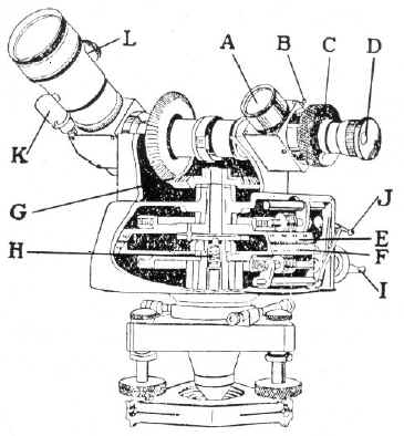 |
A. Wide angle objective B. Lever to select objective C. 100 division gradicule assembly & knurled ring D. Eyepiece E. Vertical circle (Elevation) F. Horizontal circle G. Miter gears to connect the telescope to the vertical circle. H. Gear spring (to avoid backlash) I. Micrometer had wheel for horizontal circle (Vertical micrometer is "cutaway in this illustration) j. Horizontal tangent screw engagement lever k. Objective reflector lamp L. Reflector control knob (allows illumination of the field and gradicule to be adjusted) |
The Watts Balloon Theodolite is a totally enclosed type of instrument as opposed to the Warren-Knight 8403, Gurley Aero and similar which are of the open frame type. Note that since this is a MK I theodolite the vertical circle is driven by the tangent screw, which drives the telescope through miter gears "G". In later models the tangent screw drives the telescope directly and the miter gear only drives the vertical circle.
In common with all other land based balloon theodolites the Watts Balloon Theodolite uses a bent optical path telescope, the horizontal part of which coincides with the horizontal axis of rotation. A secondary wide-angle telescope is also provided having the objective A, and using the same eyepiece D as the main telescope. This is brought into use by rotating a mirror into the line of site by means of a small lever B. The wide angle objective assists in keeping the balloon in view during the first minute of a flight, when its angular motion relative to the observer is likely to change rapidly. The knurled ring C is used to rapidly move telescope in the vertical axis. The eyepiece D can be moved independently, in order to focus the gradicule. In order to bring the vertical circle E into close proximity to the horizontal circle F, it is connected to the telescope by a pair of miter gears G. As a result both circles are visible and can be read in whole degrees through one window directly under the eyepiece. These circles are driven by tangent screws connected to hand wheels with micrometers one shown at I. The tangent screws are disengaged by levers one shown at J directly above the hand wheel I so that the telescope may be moved rapidly in azimuth or altitude. A spring H pushed the gears into contact in order to avoid backlash and take up wear.
A switched lamp is provided to illuminated the scales, and another switched lamp is provided to throw an adjustable amount of of light into the field of view. This second lamp is carried in a shield K and illuminates a small inclined reflecting surface carried on a stem projecting into the telescope barrel. The stem can be turned by a knurled head L, enabling the illumination in the field to be varied continuously from zero. The batteries for illumination are carried in a case that mounts to the top part of the instrument (not shown).
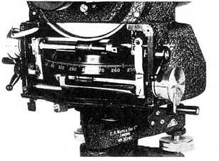 |
Cutaway of a Watts MK III (Left) shows the tangent screw
driving the vertical telescope gear, as opposed to the tangent screw
driving the vertical circle as in the Mark I cutaway above.
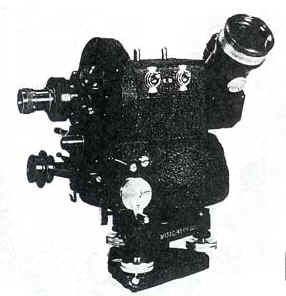
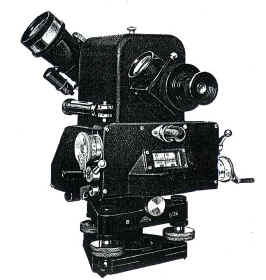
Note that the shape of the instrument has changed to accommodate a 360 tooth vertical telescope gear. Mark IIII instrument below left versus Mark I instrument below. |
 |
 |
Acknowledgement: The information was taken from "Meteorological Instruments, Third Edition - Revised, W.E.K. Middleton, A.F. Spilhaus, University of Toronto Press 1953" As well as Met Office Met. O. 804, and "THE PILOT BALLOON THEODOLITE OF THE METEOROLOGICAL OFFICE" published by E. R. Watts & Son LTD. date unknown.